


Article Contents:
- Geometric wall design: basic principles
- Wooden cladding: basic geometric module
- Patterned and corner claddings: complex lines
- Oak and beech beams: structural construction
- Strips and beams: transitional format
- Small elements: oak strip
- From flat surfaces to relief compositions
- Node examples: panel, portal, decorative block
- Conclusion: precise geometry from STAVROS
- Frequently Asked Questions

Geometric precision — the foundation of quality wooden cladding. A wall divided into panels of strictly rectangular shape with ideal 90-degree angles is perceived as the result of professional work. The same wall with deviations of 2-3 degrees creates an impression of carelessness, craftsmanship, cheapness.Wooden moldingDivides surfaces into geometric sections, creating structure.Oak beamForms a structural frame, ensuring a flat surface.wooden boards and beamsCreate intermediate elements between solid beams and thin cladding.Oak trimCover small nodes, fix details. All theseWood Trimelements work as a unified system, transforming flat surfaces into complex relief compositions with flawless geometry. Let's explore how to design and implement wooden cladding with precision down to the millimeter.


Geometric wall design: basic principles
Geometric wall cladding design begins with analyzing basic surfaces. Perfectly flat walls do not exist in real construction. Deviations from vertical 5-10 mm over a height of 2.7 meters are typical for panel buildings. Surface irregularities (bulges and depressions) of 3-7 mm are normal for monolithic construction. Brick walls may have deviations up to 15-20 mm. The task of geometric design is to compensate for these defects, creating an ideally flat finish surface.
The basic tool for compensating irregularities — a beam grid.Oak beamorOak timber beamWith a cross-section of 30x40, 40x40, or 50x50 mm, it is mounted vertically or horizontally on the wall with a spacing of 400-600 mm. Each beam is leveled using shims (plywood, plastic wedges) or by trimming protruding sections. The result — an ideally flat surface formed by the ends of the beams, to which finish elements are attached.
The flatness of the grid is checked using a long straightedge (2-3 meters) or a laser level. The straightedge is placed against the ends of the beams at various points and directions. The gap between the straightedge and the beams should not exceed 1-2 mm. The laser level creates a plane of light, along which all beams are set. The accuracy of the laser method is higher — error not exceeding 0.5 mm per 10 meters.
Modular grid — a coordinate system on which all cladding elements are positioned. The basic module is usually 100, 150, or 200 mm. All panel dimensions, spacing between claddings, and strip placement are multiples of the basic module. This creates visual order, simplifies calculations, and minimizes material cutting. A wall 3600 mm long with a basic module of 150 mm is divided into 24 modules, allowing, for example, to create 4 panels of 6 modules (900 mm) each.
Proportional systems define the relationships between element sizes. The golden ratio (1:1.618), classical proportions (2:3, 3:4, 3:5) create a harmonious perception. A panel 900 mm wide should have a height of 1350-1500 mm to comply with the 2:3 or golden ratio. The cladding dividing this panel into sections should create similar proportions within.
Symmetry and asymmetry — tools for creating composition. The classical approach tends toward symmetry: the wall is divided into equal panels arranged mirror-symmetrically relative to the central axis. The modern approach allows asymmetry: panels of different sizes, offset from the center, creating a dynamic composition. But even asymmetry should be thought out, adhering to visual balance rules.
Technical limitations affect geometry. Maximum lengthof wooden stripswithout joints — usually 3-4 meters. For longer spans, either a micro-tenon joint (toothed connection) or joining multiple elements is required. The joint should fall on a grid beam so both ends have support. Planning the placement of joints — part of geometric design.
Wooden cladding: basic geometric module
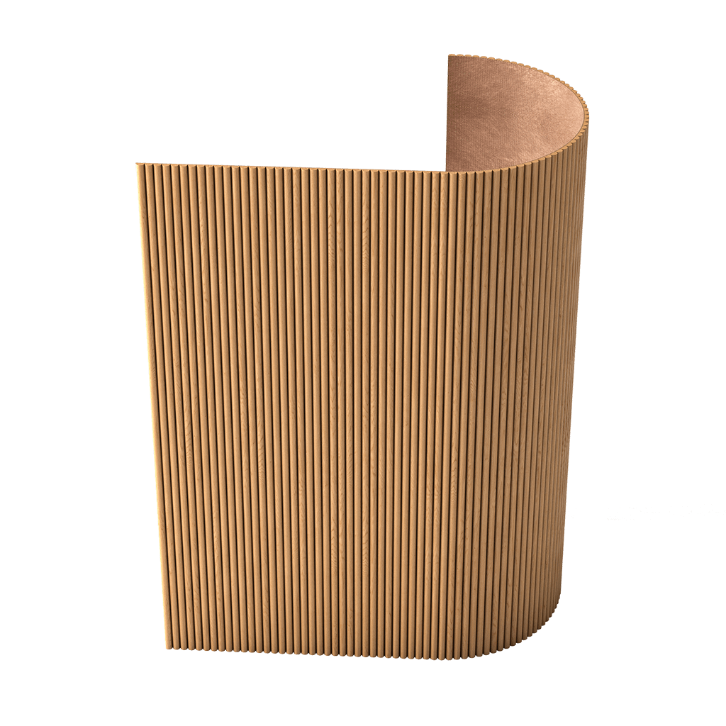
Wooden molding— a thin strip 20-40 mm wide and 8-15 mm thick, creating linear divisions on surfaces. The geometric role of cladding — dividing the plane into sections of regular shape. A 100x150 cm rectangular panel without cladding is perceived as a monolithic surface. The same panel, divided by cladding into 6 sections of 50x50 cm, acquires structure, visual interest, and scale.
The dimensions of the panel layout are determined by the scale of the surface. For small panels 60x80 cm, a layout width of 20-25 mm is suitable — it is noticeable but not overpowering. For medium panels 100x150 cm, the optimal width is 25-35 mm. For large panels 150x200 cm, a layout width of 35-45 mm is required to avoid being lost on a large surface. Rule: the width of the layout should be 1/40 - 1/30 of the shorter side of the panel.
The thickness of the layout affects visual weight and relief depth. A thin layout of 8-10 mm creates a delicate division, almost graphic. Medium thickness of 12-15 mm — a universal solution, creating noticeable relief without excessive bulk. Thick layout of 18-22 mm forms an expressive structure with strong shadows, suitable for large surfaces.
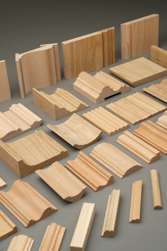
The layout profile can be flat rectangular or shaped. FlatOak veneerwith sharp edges — for minimalism and modern interiors. Layout with one bevel at 45 degrees — an intermediate option, softening edges. Layout with a 3-5 mm radius rounding — for neoclassical and traditional styles. Complex shaped layout with multiple tiers — for classical and baroque interiors.
The layout is attached to the surface using carpentry glue with additional fixation by finish nails 20-30 mm long. Nails are driven in at 300-400 mm spacing, strictly perpendicular to the surface. Nail heads are countersunk 1-2 mm using a nail set. Grooves are filled with wood-colored putty (for natural finish) or base putty (if the layout will be painted). After drying, surfaces are sanded smooth with fine abrasive.
Corner joints of the layout — a critical node determining the quality of work. A 45-degree joint with matching profiles — the gold standard. The joint is milled on a miter saw with precision to 0.5 degrees. Any deviation creates a noticeable gap. After milling, elements are dry-fitted for checking. A quality joint has no gap, and the profile flows continuously from one element to another. Then elements are glued and secured with nails.
Geometric layout schemes vary from simple to complex. The simplest — a rectangular grid of horizontal and vertical layouts, dividing the panel into equal sections. More complex — concentric frames around a central element. Even more complex — diagonal grid, where layouts are placed at 45-degree angles. The most complex — curved schemes with oval and circular elements, requiring bending or assembly from short segments.
Our factory also produces:


Shaped and corner layouts: complex lines
wooden veneer with a decorative profilehas a profiled cross-section with rounded edges, ovals, grooves, creating volume and play of light and shadow. Shaped profile is more complex to manufacture — requires milling on special machines with precise tool positioning. But the result justifies the effort: shaped layout creates a rich, detailed surface characteristic of classical interiors.
Types of shaped profiles are diverse. Layout with one rounded edge (oval) — the simplest shaped profile, creating a soft convex line. Layout with an oval (concave profile) — creates a recess where shadows collect. Layout with a combined profile (oval + oval + flat flange) — a complex three-tiered profile, creating rich form play. Carved layout with floral or geometric motifs — the pinnacle of decoration, characteristic of baroque and rococo.
Wooden corner veneer— a special element for decorating external and internal corners. Corner layout has an L-shaped cross-section with two flanges adjacent to adjacent planes. External corner layout is often rounded or beveled, creating a safe and visually soft transition. Flange width 20-30 mm each, total width of the element in unfolded form 40-60 mm.
Functions of corner layout: protection of the corner from mechanical damage, decorative treatment of transitions between planes, hiding possible gaps at panel joints. Oak or beech corner layout does not deform from impacts, retains geometry, and can be easily restored by sanding if needed. This is critical for external corners of walls, columns, and portals, which are often subjected to accidental collisions.
Installation of corner layout requires precision. Both flanges must fit tightly against surfaces without gaps. If the wall angle is not exactly 90 degrees (a 1-2 degree deviation is typical), the layout is adjusted: either the internal angle of the profile is milled, or compensating shims are used. Fixation with glue and additional nail fixation in both flanges. Fixation points are filled with putty and sanded.
Beech trimis preferred for shaped profiles due to uniform wood grain structure. Beech is milled cleaner than oak — fewer splinters, smoother surface after processing. For complex carved profiles, beech is practically the only option. Oak layout, with its more pronounced grain, works better in flat and simple shaped profiles, where wood grain is part of the decorative effect.
Bending of layout for creating curved elements is possible but complex. Thin layout 8-10 mm thick beech can be bent to a radius of 1000 mm after pre-soaking or soaking. Thicker layout requires radii of 1500 mm. For smaller radii, layout is assembled from short straight segments connected at small angles — a polygon imitates a curve. Alternatively, bent-glue technology is used, where layout is glued from thin laminates bent on a template.
Get Consultation
— structural element for geometrically precise wooden finish. Beam forms a load-bearing frame — a substructure to which finish elements are attached. The final result depends on the accuracy of the beam geometry and quality of substructure installation. Even perfectly manufactured layout cannot save the situation if it is attached to a curved substructure.
Oak beam— the basis of geometrically precise wooden finishing. The beam forms a load-bearing frame — a substructure to which finishing elements are attached. The final result depends on the accuracy of the beam's geometry and the quality of the substructure installation. Even perfectly manufactured layout will not save the situation if it is mounted on a warped substructure.
Requirements for beams for substructure are strict. Moisture content no more than 10% — beams with higher moisture will dry after installation, deforming the entire structure. Straightness — deviation from straight line no more than 2 mm per 3 meters of length. "Twist" (twisting along longitudinal axis) no more than 2-3 degrees per 3 meters. Section accuracy ±0.5 mm — critical for creating a flat surface with beam ends. Absence of knots with diameter over 10 mm — knots create rigid zones that may crack under fastener installation.
Oak timber beam— alternative to oak at lower budget. Beech beam is 20-30% cheaper than oak with comparable characteristics. For hidden structures (substructure under panels, frames that will be fully covered), beech is optimal. For visible structures (exposed beams, frames), oak is preferred due to more expressive grain.
Beam sections for substructure are chosen based on the task. For substructure under thin panels (MDF 6-10 mm, gypsum board 12 mm) without insulation, a 30x40 or 40x40 mm beam is sufficient. For panels with insulation (mineral wool 50 mm), a 50x50 mm or 40x60 mm beam is required to create sufficient clearance for insulation. For heavy panels (solid wood, thick MDF 16-20 mm), a 50x50 mm or 60x60 mm beam is needed to ensure structural strength.
Substructure spacing (distance between beams) is determined by the rigidity of the finish material. For rigid panels (MDF 16-20 mm, solid wood), spacing of 600-800 mm is sufficient. For flexible materials (gypsum board 12 mm, thin MDF 6-10 mm), spacing of 400-500 mm is required to avoid sagging. For lath structures, spacing is determined by the length of the laths — typically 600-800 mm, so each lath rests on at least 3 beams.
Beam attachment to wall is done with wall plugs and self-tapping screws at 600-800 mm spacing. Wall plug is selected based on wall material: for concrete — spread nylon, for brick — extended spread, for hollow blocks — special wall plug with side expansion. Self-tapping screw 70-100 mm long passes through the beam, wall plug, and embeds into the wall to a depth of 50-60 mm. Screw head is countersunk flush or 1-2 mm below the beam surface.
Substructure leveling — critical stage. Laser level is used, creating a plane of light. First beam is set strictly vertical (for vertical substructure) or horizontal (for horizontal) using a standard bubble level. Laser level is mounted on this first beam, creating a base plane. All other beams are set so their ends touch the laser plane. Wall irregularities are compensated with shims under beams or by trimming protruding sections.
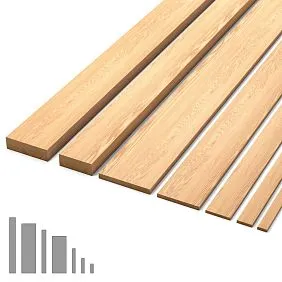
— intermediate cross-section elements between heavy beams (50x50 mm and larger) and thin layouts (20-40x8-15 mm). Typical lath-beam cross-sections: 30x30, 40x40, 30x50, 40x50 mm. These elements combine the structural strength of beams with the decorative possibilities of laths.
wooden boards and beams— intermediate sections between solid beams (50x50 mm and larger) and thin layouts (20-40x8-15 mm). Typical cross-sections of lath-beams: 30x30, 40x40, 30x50, 40x50 mm. These elements combine the structural strength of beams with the decorative possibilities of laths.
Functional versatility of lath-beams makes them popular. They can serve as substructure elements for light panels. Simultaneously — as finish decorative elements, forming visible structure.Solid beech parquetwith 40x40 mm cross-section works both as support and as part of composition.
Application in framed structures — classic carpentry. Frame made of 40x40 mm beams with grooves for inserting panels creates the structure of a classic panel or door. Beams are joined with tongue-and-groove: a tongue is cut on one beam end, a groove on another. Elements are joined without fasteners using PVA carpentry glue. Strength of such a joint exceeds the strength of the wood itself.
Decorative frames made of lath-beams create geometric structure on walls. Frame made of 30x50 mm beams frames a wall section, inside which another finish — wallpaper, fabric, painted MDF — is applied. Beams are mounted flat (wide side up), creating a 50 mm protrusion. Corner joints at 45 degrees with gluing and additional fixation with self-tapping screws from the back side.
Lattice structures made of lath-beams form delicate screens. 30x30 or 40x40 mm beams form a grid with 100x100, 150x150, or 200x200 mm cells. Joints are made in half-depth: grooves are cut at the intersection of beams to half the thickness, beams are inserted into each other. The structure becomes interconnected, strong, and visually light.
Buy wooden skirting boardTransition sections are suitable for projects requiring versatility. One size (e.g., 40x40 mm) is used both for the substructure and for finishing elements. This simplifies ordering, reduces the number of sizes on-site, and speeds up installation. The time savings and reduced risk of errors justify this approach.
The finish of lath-beams is determined by their role. Hidden substructure elements are not painted — protective impregnation with antiseptic is sufficient. Visible decorative elements are painted according to interior design concept: natural color under lacquer, staining with dyes, or solid color. Simultaneous structural and decorative roles require finishing of all visible surfaces.
Small elements: oak lath
Oak trim— the smallest element of the trim system, but its role in creating precise geometry is critical. The lath fixes glass, covers small joints, and creates finishing details. The lath cross-section is 10x10, 12x15, 15x20 mm — miniature dimensions require precision in manufacturing and installation.
The function of glass fixation — the primary application of the lath. Glass is installed into a groove of the frame (door, window, furniture), pressed against the frame by the lath, which is fixed with finishing nails 20-25 mm long. The lath creates mechanical clamping, preventing glass from falling out due to vibration or impact. Silicone sealant under the glass ensures airtightness, while the lath provides mechanical reliability.
Geometric precision of the lath is critical. The cross-section must be strictly rectangular or precisely match the drawing (if the profile is shaped). A deviation of 0.5 mm creates a gap between the lath and the frame, through which the back side of the glass and sealant are visible. Straightness — deviation no more than 1 mm per meter of length. A curved lath does not fit the frame evenly, creating gaps.
The lath profile can be flat rectangular or shaped with rounding. A flat lath with a 10x10 mm cross-section — for minimalism. A shaped lath with a 3 mm radius rounding on the front face — for traditional and classic interiors. A complex shaped lath with multiple tiers — for luxurious interiors with detailed joinery.
Lath mounting is performed with finishing nails 20-25 mm long, spaced 150-200 mm apart. The nail is driven at a slight angle (10-15 degrees from perpendicular) to clamp the lath to the frame and simultaneously fix the glass. The nail head is pressed in 1 mm, and the indentation is filled with putty. Oak lath holds nails securely without cracking due to dense wood structure.
Corner connections of lath in frames with glass are made at 45 degrees. Cut on a circular saw with precision to 0.5 degrees. A quality lath joint is invisible — it creates the impression of a monolithic frame around the glass. A poor joint with a gap spoils the entire impression of the item, even if the rest of the work is flawless.
Lath finish always matches the frame finish — doors, windows, furniture. The lath and frame are perceived as a single unit. Even a 1-2 tone difference is noticeable against transparent glass. The best way to ensure matching is to paint the frame and lath simultaneously from the same paint or lacquer can.
From flat surfaces to relief compositions
Transforming a flat wall into a relief composition — the process of adding geometric elements that create volume, depth, and visual interest. The base wall — a flat painted surface. First level of complexity — moldings or layouts dividing the wall into panels. Second level — filling panels with material different from the background (different color, texture, relief). Third level — adding protruding elements (outlets, carved inserts, relief panels).
Relief depth determines the visual strength of the composition. Fine relief 10-15 mm (thin layout on a flat surface) creates a delicate structure, noticeable under side lighting. Medium relief 20-30 mm (layout and inset filling or protruding elements) forms a clearly readable volumetric composition. Deep relief 40-60 mm (multi-level constructions with substructure, panels, protruding elements) creates a dramatic, sculptural effect.
Play of light and shadow — the basis of relief perception. Protruding elements cast shadows onto recessed areas. Recessed areas accumulate shadows and appear darker. As lighting changes (morning, day, evening), the relief is perceived differently. In the morning, slanted rays highlight every detail. During the day, diffused light equalizes the structure. In the evening, directional lights create deep contrasting shadows.
Material diversity enhances the effect. Layout made of natural oak under lacquer frames panels filled with painted MDF or fabric. Texture contrast — live wood against smooth paint — creates richness of perception. All wooden elements from the same species (oak) form material unity despite visual diversity of fillings.
Color contrasts enhance relief. Light layout on a dark background emphasizes panel geometry, making the structure graphic. Dark layout on a light background creates the reverse effect — frames protrude, fillings recede. Monochromatic solution (layout and filling of one color) builds relief only on physical protrusion of elements, without color cues.
Transition from flat to relief is performed step by step. Design — creating drawings specifying all dimensions, depths, materials. Installing substructure — creating a base plane and frame for panels. Installing panels — filling sections between substructure beams. Installing layout — creating panel boundaries. Adding protruding elements — final detailing. Finishing — painting, lacquering, patination.
Node examples: panel, portal, decorative block
Node "wall panel with layout" — basic unit of geometric finishing. Construction: substructure of 40x40 mm beams with 600 mm spacing, creating a plane. Filling — 10 mm MDF, painted to required color, fixed to substructure. Panel perimeter is framed by 30x12 mm layout, mounted over MDF. Inside the panel — additional 25x10 mm layout dividing it into sections. All layout corner joints at 45 degrees. Total construction depth from base wall — 50-60 mm (40 mm beam + 10 mm MDF + 12 mm layout).
Node "door portal with framing" — architectural element transforming the opening into a significant dominant. Construction: door frame 100 mm wide, casing 90 mm wide. Additionally, around the casing, a frame of 40x50 mm lath-beams is mounted flat (50 mm protrusion). The frame creates a portal width of opening + 2 x (90 mm casing + 100 mm setback + 40 mm frame) = opening + 460 mm. Height is similar. Inside the frame between casing and beams — contrasting color or texture filling. Total portal depth from wall — 50 mm (frame protrusion), creating an expressive volumetric structure.
Node "decorative block on wall" — accent element attracting attention. Construction: on the wall, a 50x50 mm beam substructure is mounted, creating a square or rectangular frame. Size, for example, 800x800 mm. Inside the frame, vertical 30x40 mm laths are mounted with 80 mm spacing. Laths create rhythmic structure. Around the frame perimeter, 35x15 mm layout is mounted, framing the entire block. Total depth from wall — 50 mm (beam) + 40 mm (lath protrusion) = 90 mm. Between laths, hidden LED strip lighting can be installed, transforming the block into a glowing object.
Node "angled protection with layout" — functional and decorative element. Construction: on the external angle of the wall or column, an L-shaped layout with 30x30 mm flanges is mounted. The external angle of the layout is rounded with a 5 mm radius. Mounting with adhesive and finishing nails into both flanges. Along the layout, at 100 mm from the angle, vertical flat layouts 25x10 mm are mounted, creating additional lines emphasizing verticality. Total decorative angle width — 260 mm (100 mm + 30 mm angled + 100 mm + 25 mm flat on each side).
Node "lath structure with beams" — imitation of classic framed panel construction. Construction: on a flat surface of a door or panel, a 40x40 mm lath-beam frame is mounted around the perimeter. Inside the frame, a cross made of the same beams divides it into 4-6 sections. Beams are mounted flat (40 mm protrusion) with adhesive and nails. In the center of each section — a protruding outlet or carved element. After painting, the structure is perceived as a single framed panel door, although it is actually a flat surface with protruding elements. Relief depth — 40 mm, sufficient for creating convincing volume.
Conclusion: precise geometry from STAVROS
Geometric precision of wooden finishing is determined by material quality and professional installation. STAVROS company offers a full range of elements for creating relief compositions:wooden panels, Oak beamandbeech, lath-beams, trim.
Premium wood, kiln-dried to 8±2%, processed on high-precision equipment with tolerance ±0.3 mm, multi-stage sanding — STAVROS standards. Each element is manufactured according to geometric precision requirements.
Oak veneer, Beech trim, Solid Wood PlanksAvailable from stock in Saint Petersburg and Moscow. Custom profiles and sizes can be manufactured according to customer drawings.
Frequently asked questions
What precision of dimensions is critical for layout? Tolerance ±0.5 mm for width and thickness. Greater deviation creates noticeable differences when joining elements.
Can pine beams be used for subflooring? Yes, first-grade pine is suitable. However, oak and beech are more stable and less prone to deformation due to humidity fluctuations.
How to ensure perfect 45-degree angles? Use a miter saw with a laser guide and precise angle adjustment. Check each cut with a speed square.
How much does a wall panel with 2 m² layout cost? 15,000–30,000 RUB including materials and installation, depending on the complexity of geometry and wood species.
Is it necessary to treat subfloor beams with antiseptic? Recommended for dry indoor spaces, but not mandatory. Required for humid environments.
Which trim to choose — oak or beech? For painting — beech (more uniform). For natural finish — oak (more pronounced grain texture).
Can layout be installed without nails, only with adhesive? Technically possible, but unreliable. Adhesive + nails — standard for quality work.


